
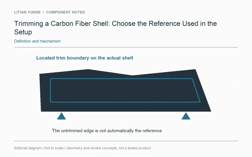
A trim outline needs a reliable relationship to the moulded shell in its actual machining setup. Define how the shell is located and supported before comparing the finished edge with the drawing. An untrimmed perimeter is not automatically a suitable reference.
Show the locating scheme
Identify the intended contact or reference features and the relevant part condition. A shell may be flexible before it is assembled, so the supported condition can matter to the operation and inspection. Keep those details with the agreed setup rather than leaving them implicit in a photograph of a fixture.
Connect the trim to the component definition
The drawing should make the finished edge, openings and assembly interfaces understandable from the controlled references. A manufacturing allowance is different from the delivered outline. If an as-moulded feature is proposed for location, review whether it represents the intended reference consistently enough for the required task.
Inspect the released condition
Agree how the finished shell is held or released when its critical features are measured. A good fit in a trim fixture is not necessarily the same result as a good fit in the final assembly. Retain the sample identity and represented setup during approval so a later tool or locating change can be reviewed against the original evidence.

For the project review: locating and supporting features; trim boundary versus allowance; required part condition; connection to final assembly references.