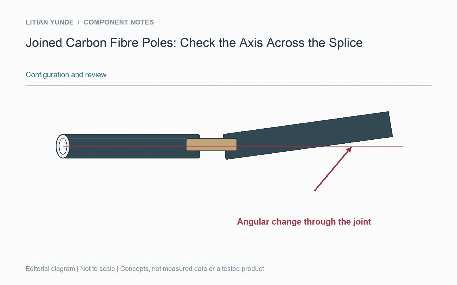
Two straight tube sections do not automatically form a straight assembled pole. The splice can introduce an offset or angular change. Define the assembled reference and measurement setup as well as the individual section requirements.
Show the joint in its evaluated state
Identify the supplied connector, engagement position and assembled section order. Mark any orientation feature used during assembly. If the connection has an adjustable position, record which position was used for the sample assessment. A loose dry assembly and a completed joint can represent different conditions.
Distinguish the possible observations
An offset at the joint and an angular change through the joint are different geometric observations. A runout check during rotation also needs its support and rotation reference. Do not compare a local tube straightness entry with a whole-pole alignment result as if they were the same measurement.
Keep the setup with the result
For a long assembly, identify support positions and the condition in which the axis is evaluated. The method and acceptance limits need engineering agreement for the actual use; this article supplies neither. When a section is replaced, retain its identity and assess the resulting assembly under the agreed method. The useful handover connects the individual members, joint configuration and whole-pole result, so the recipient can understand what was actually checked.