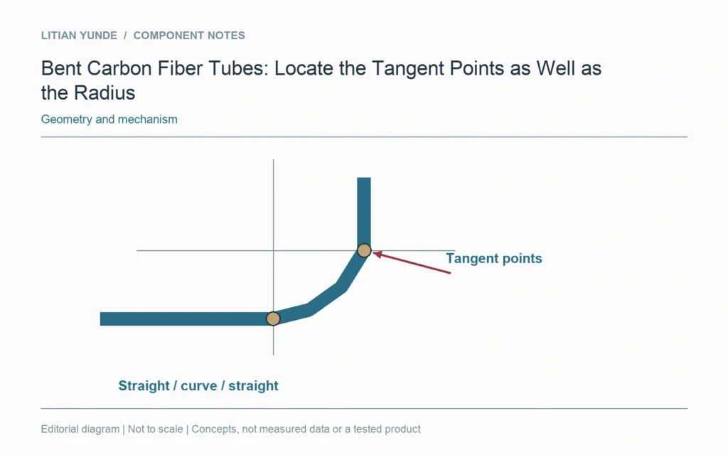
A bend radius does not fully locate a bent tube’s straight ends. Identify the tangent points and the straight lengths or other controlled dimensions needed by the assembly. Keep those references consistent with the centreline or surface-radius convention on the drawing.
Show where the curve starts and ends
Mark the transition from each straight portion to the intended bend. If the drawing uses a centreline model, keep its tangent positions distinct from the outside envelope. A total end-to-end span can describe the package size without revealing the usable straight mounting length.
Include the receiving interfaces
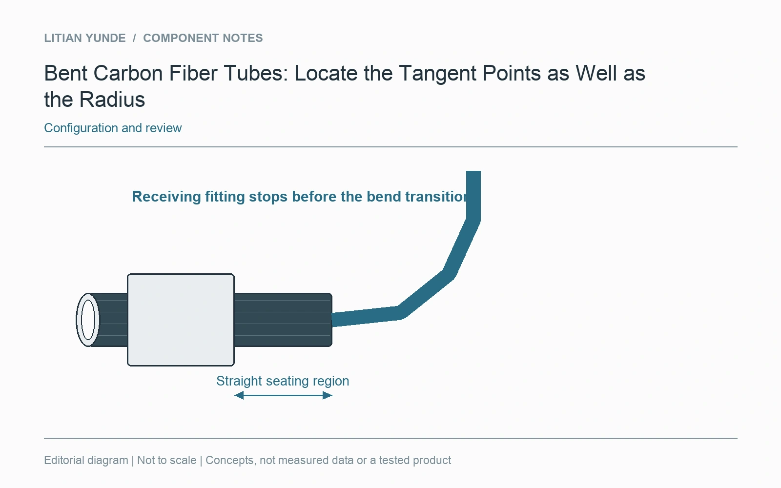
Show the region that enters a clamp, socket or fitting on each end. A bend placed closer to one fitting can leave the same nominal radius while changing the available seating length. Retain orientation references where features at the ends also need clocking.
Inspect the agreed geometry
Define which dimensions control acceptance and how the tube is supported during the check. Do not derive an omitted tangent location by measuring a scaled picture. If the supplier proposes a different straight-to-curve transition, review it as a geometry proposal. The sample should represent the complete end and bend arrangement needed for the installation.