qunhe

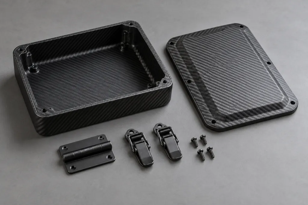
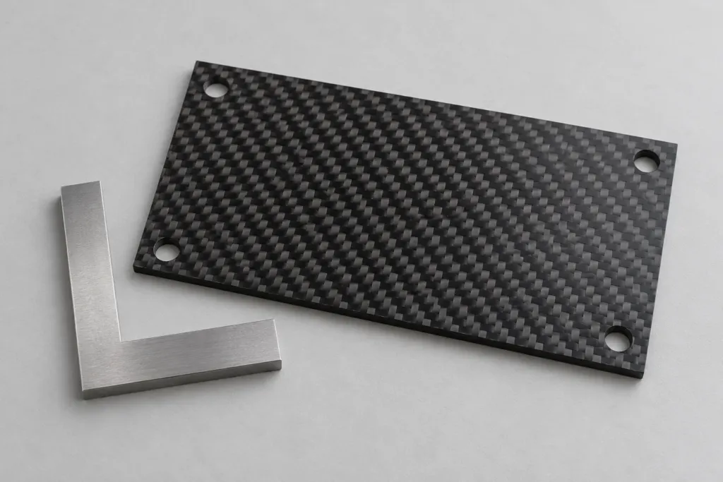
Concept illustration of Carbon Fiber Shell Flanges: Check Access to the Back of the Fastener

Carbon Fiber Shell Flanges: Check Access to the Back of the Fastener

A visible fastener hole does not prove a shell flange can be assembled. Check where the nut or retainer sits, how a tool reaches it and whether neighbouring parts block access. Review the installation and removal sequence before accepting the flange geometry, especially when the completed equipment encloses its underside.

Carbon Fiber Shell Flanges: Check Access to the Back of the Fastener Read More »

Concept illustration of Customer-Supplied Hardware for Carbon Fiber Parts: Define the Handover

Customer-Supplied Hardware for Carbon Fiber Parts: Define the Handover

When a customer supplies hardware for a carbon fiber assembly, record exactly what is handed over, what the supplier is expected to do with it and how unused or unsuitable items are handled. Hardware ownership alone does not define inspection, storage, assembly, loss reporting or replacement responsibility.

Customer-Supplied Hardware for Carbon Fiber Parts: Define the Handover Read More »

Concept illustration of Ventilated Carbon Fiber Covers: Open Area Is Not a Cooling Result

Ventilated Carbon Fiber Covers: Open Area Is Not a Cooling Result

Vent slots define an opening geometry, not a verified cooling performance. Review the heat sources, airflow route, installed orientation and nearby components before approving a ventilated carbon fiber cover. Keep vent dimensions and any thermal test result as separate requirements for the specific completed configuration.

Ventilated Carbon Fiber Covers: Open Area Is Not a Cooling Result Read More »

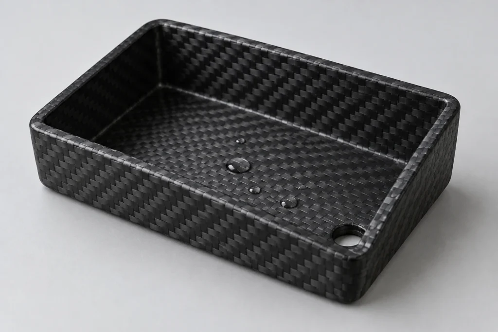
Concept illustration of Carbon Fiber Protective Covers: Review Drain Paths in the Installed Position

Carbon Fiber Protective Covers: Review Drain Paths in the Installed Position

A drain opening is useful only when water can reach it and leave the installed assembly. Review the cover’s actual orientation, low points, nearby supports and service condition. A hole visible on a loose shell does not prove the assembled cover drains, and drainage does not establish a waterproof or ingress-protection rating.

Carbon Fiber Protective Covers: Review Drain Paths in the Installed Position Read More »

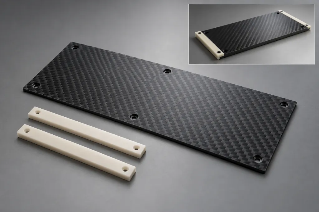
Concept illustration of Carbon Fiber Panels with Wear Pads: Specify the Replaceable Contact Part

Carbon Fiber Panels with Wear Pads: Specify the Replaceable Contact Part

If repeated contact occurs on a carbon fiber panel, define the contacting pad or strip as a separate part of the assembly. Specify its material, location, attachment and replacement condition. Do not assume exposed carbon laminate is the intended wearing surface, or that an added pad automatically proves a service life.

Carbon Fiber Panels with Wear Pads: Specify the Replaceable Contact Part Read More »

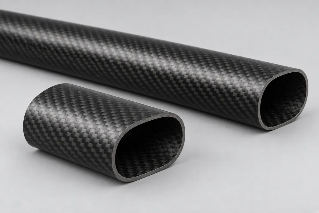
Concept illustration of Carbon Fiber Tube Bores: End Measurements Do Not Describe the Full Passage

Carbon Fiber Tube Bores: End Measurements Do Not Describe the Full Passage

Measuring a carbon fiber tube bore at each end does not establish the condition of every section between them. State what the bore must do, where measurements are required and which regions the chosen method can reach. For a sliding insert or routed cable, a separate functional passage check may also be necessary.

Carbon Fiber Tube Bores: End Measurements Do Not Describe the Full Passage Read More »

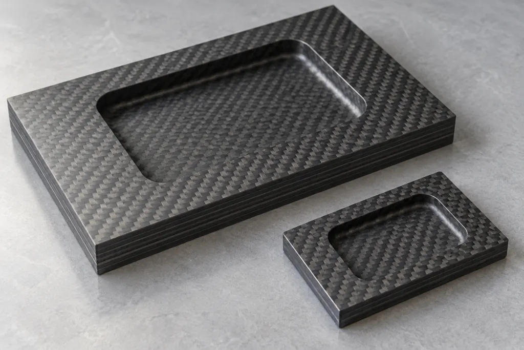
Concept illustration of Machined Pockets in Carbon Fiber Plates: Specify the Remaining Wall

Machined Pockets in Carbon Fiber Plates: Specify the Remaining Wall

A pocket depth does not describe the material left beneath a recess. Define the local finished plate thickness, the depth reference and the required remaining wall together. Review the laminate and intended loads with the responsible engineer before removing material; a tidy pocket surface does not establish structural adequacy.

Machined Pockets in Carbon Fiber Plates: Specify the Remaining Wall Read More »

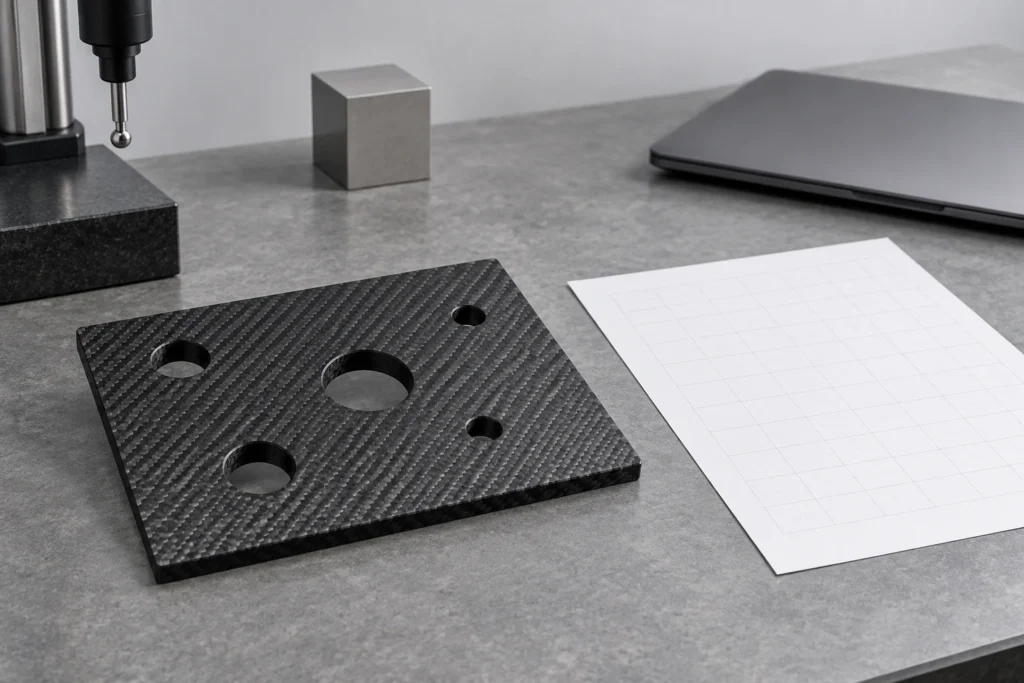
Concept illustration of Datums on Carbon Fiber Plates: Agree the Reference Before Comparing Hole Positions

Datums on Carbon Fiber Plates: Agree the Reference Before Comparing Hole Positions

A hole-position report is meaningful only when the reference system is clear. For a carbon fiber plate, identify the locating face, reference edges or holes, and the inspection condition. Two teams can measure the same part and obtain different coordinates if they establish different origins or rotate the part differently.

Datums on Carbon Fiber Plates: Agree the Reference Before Comparing Hole Positions Read More »