

A transport rack introduces its own contact and restraint conditions. A carbon fiber component supported correctly in service may meet a small pad or a strap in a very different place during transport. Review that configuration separately from the operating assembly.
Mark every point that touches the part
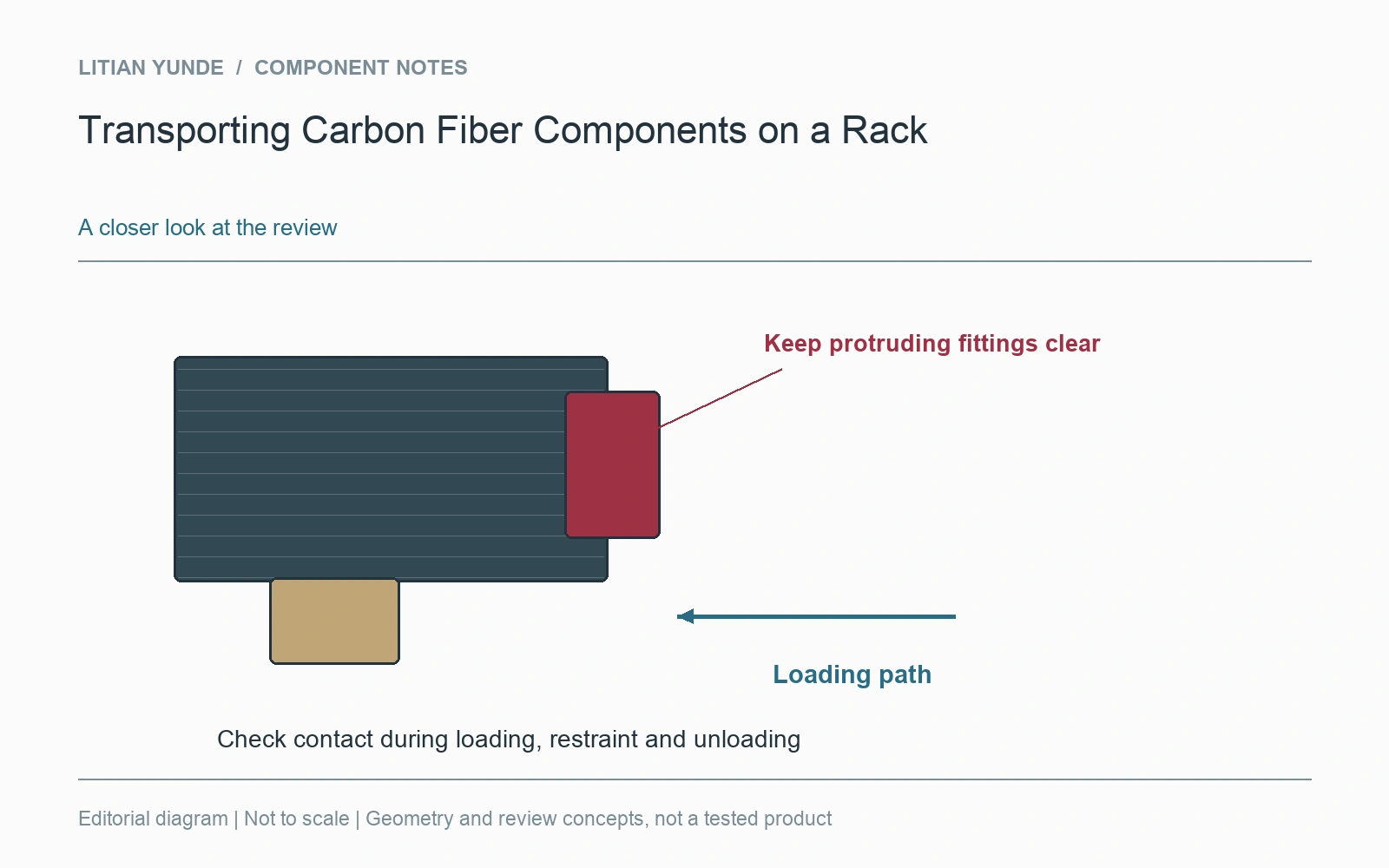
Show the support pads, stops and restraints on the rack layout. Include the direction of gravity in the transported position. An apparently broad support may touch only an edge or a protruding fitting. If the rack carries several parts, check whether they can touch each other when restrained or moved.
Restraint and cushioning do different jobs
A pad can separate surfaces without preventing movement; a strap can prevent movement while introducing local contact pressure. Review those functions together. Do not specify tightening by feel or assume the torque used in an operating clamp applies to a transport restraint. The contact region and the forces differ.
Keep movement away from vulnerable features
Cable openings, exposed edges, small bosses and visible finishes may need clearance from the rack. Make that clearance practical during loading as well as after the part is secured. If removable fittings are shipped separately, identify them and preserve the assembly information. A restraint layout that depends on a fitting remaining installed should be recorded as such.
Use a real loading trial to close the loop
With the intended rack and a suitable sample, review loading access, restraint placement and unloading. Retain photographs of the completed configuration. If transport performance needs validation, define that test separately rather than treating a loading photograph as proof against shocks or vibration. For repeat shipments, the accepted rack configuration should be tied to the component revision.
For the project review: support and restraint contact map; loading and unloading clearance; protection for exposed features; rack configuration and part revision.