
Tubes & Interfaces · Component review guide · Litian Yunde
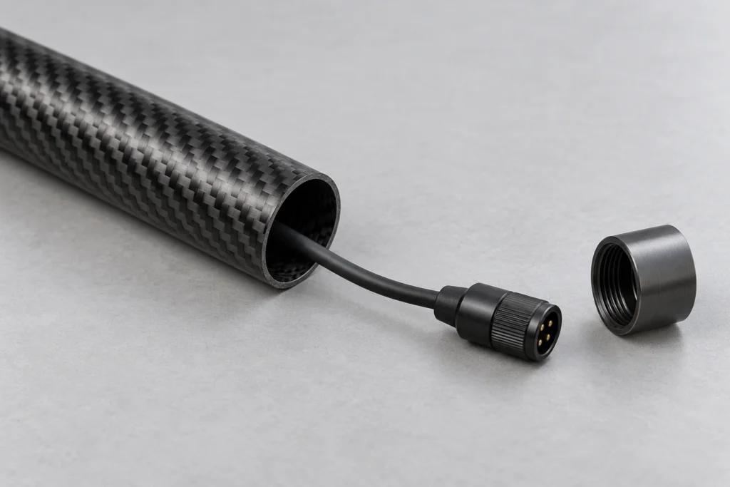
AI-generated explanatory concept; not a Litian Yunde product photograph or a validated design.
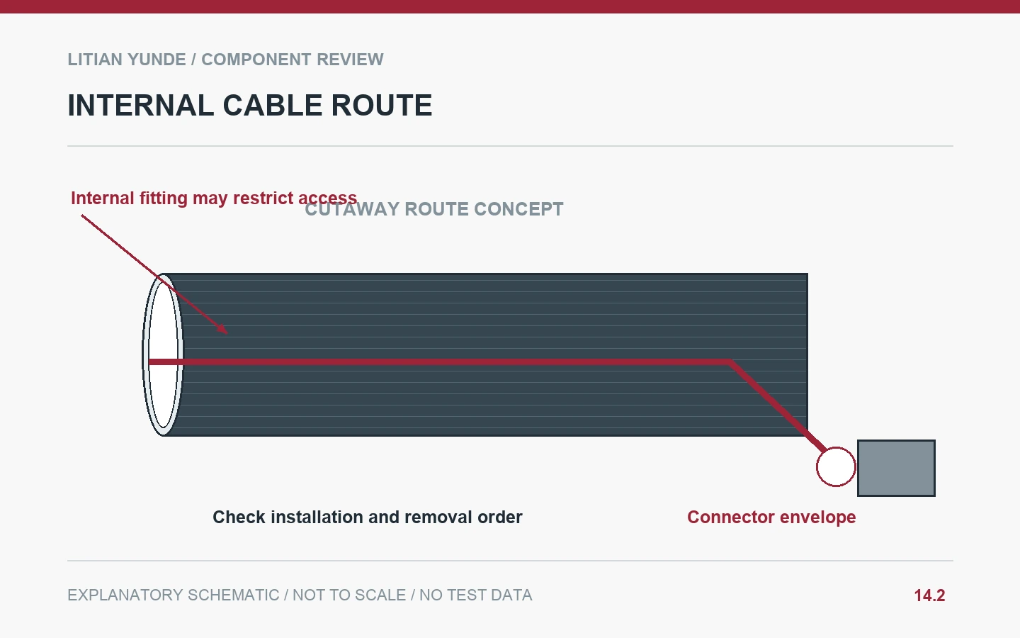
A cable route through a carbon fiber tube must work for installation and service, not only for the cable’s bare diameter. Check the connector envelope, internal route, exits and support points. Define the order in which fittings and cables are installed, and keep electrical protection requirements separate from geometric passage.
Include the connector and fittings
Identify the largest item that needs to pass through the tube, including connector locks or protective sleeves. An end fitting can reduce the usable opening even when the loose tube bore is large enough. Review the actual direction of installation. If a connector is attached after routing, identify that operation and who supplies it. Do not assume the cable can be pulled through a finished assembly because it fits a short sample tube.
Review exits and internal contact
Show where the cable leaves the tube and how it is supported near the exit. Agree bend and strain-relief requirements with the cable or equipment designer instead of inventing a radius. Check whether an internal fitting, adhesive region or fastener obstructs the route. Specify any approved protective interface. A smooth-looking carbon surface does not automatically establish electrical isolation or protection against repeated rubbing.
Make the route reversible where service requires it
Define whether a cable can be removed without destroying a bonded end fitting or modifying the tube. Record any removable parts and the order of disassembly. Keep spare cable and connector references linked to the compatible tube assembly. A successful pull-through trial can support the defined route, but it does not validate electrical function, insulation durability or all operating movement.
Example: the connector arrives last
A supplier checks a cable through the loose tube, then bonds an end fitting that prevents the finished connector passing. The revised assembly plan reviews the connector envelope and installation order before bonding. It also identifies whether later cable replacement is possible, avoiding an undocumented assumption that the tube will be cut open for service.
Illustrative scenario, not a customer case or reported production result.
Details to agree before ordering
| Review item | Record to agree |
|---|---|
| Envelope | Cable, connector, locks and sleeves. |
| Route | Bore, fittings, exit direction and obstructions. |
| Protection | Approved support, bend and strain-relief details. |
| Service | Removal sequence and replacement compatibility. |
Questions buyers ask
Does bore clearance establish electrical isolation?
No. Electrical requirements and protective interfaces need their own specified evidence.
Can routing be checked with the cable alone?
Only if that represents the agreed installation. Include connectors or later termination operations where relevant.
Technical background and related reading
Background resource: Hexcel: Composite Engineering Resources. Background reading only; the project checklist is editorial guidance, and this reference does not establish supplier certification or part approval.
- Cable Openings in Carbon Fiber Covers: Grommet and Edge-Clearance Details
- Carbon Fiber Tube Bores: End Measurements Do Not Describe the Full Passage
- Browse the carbon fiber knowledge centre
Review your component with Litian Yunde
Share the drawing revision, intended application and the interface or inspection question you need to resolve. The quoted construction and acceptance requirements are confirmed for the specific project.