

Machining & Assembly · Component review guide · Litian Yunde
AI-generated explanatory concept; not a Litian Yunde product photograph or a validated design.
A visible fastener hole does not prove a shell flange can be assembled. Check where the nut or retainer sits, how a tool reaches it and whether neighbouring parts block access. Review the installation and removal sequence before accepting the flange geometry, especially when the completed equipment encloses its underside.
Show both sides of the connection
Provide a section or assembly view that includes the flange, mating bracket, fastener, washer and retainer. A top view can conceal a return edge or a neighbouring wall beneath the joint. Identify the hardware configuration that governs the space. Do not substitute a guessed fastener head or washer profile in the review. If a captive retainer is proposed, define its supplied scope and how it is located.
Check the working envelope of the tool
Allow for the tool actually used to hold and turn the hardware, including the approach and withdrawal route. A static gap around a nut may not allow the intended socket or spanner to reach it. Review whether surrounding parts must be installed later or temporarily removed. Do not count on bending the flange or using uncontrolled assembly force to create tool space. The approved method should be feasible without changing the part.
Repeat the review for service removal
Installation access can disappear after cables, trays or adjacent covers are fitted. If the fastener is intended to be removed in service, check the complete service configuration and explain which items must first be removed. A permanent captive component needs its own replacement route. Fit confirmation and tool-access checks belong in the assembly record; neither supplies an unverified clamp load or structural rating for the flange.
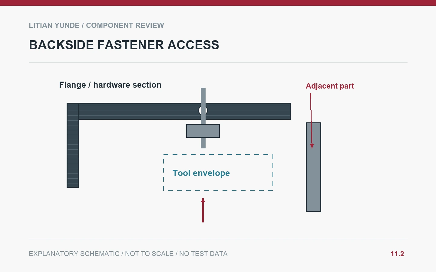
Example: the trapped washer
A sample shell fits its bracket, but a washer cannot be placed behind the flange once the internal tray is installed. The team revises the controlled assembly sequence and reviews whether service removal remains possible. The solution is documented instead of leaving installers to omit the washer or enlarge the hole.
Illustrative scenario, not a customer case or reported production result.
Details to agree before ordering
| Review item | Record to agree |
|---|---|
| Section | Both sides of flange and mating hardware. |
| Tools | Approach, turning and withdrawal envelope. |
| Sequence | Parts installed before and after fastening. |
| Service | Removal route in completed equipment. |
Questions buyers ask
Can a tool-clearance problem be solved by omitting a washer?
Only an authorised connection change can alter the specified hardware. Record the interference and obtain disposition.
Does tightening the screw prove the flange joint is valid?
It shows an assembly action. The connection still needs its agreed fit, method and performance evidence.
Technical background and related reading
Background resource: Hexcel: Composite Engineering Resources. Background reading only; the project checklist is editorial guidance, and this reference does not establish supplier certification or part approval.
- Clearance Holes and Countersinks in Carbon Fiber: Define the Hardware Interface
- Carbon Fiber Covers with Seals: Define the Installed Compression Condition
- Browse the carbon fiber knowledge centre
Review your component with Litian Yunde
Share the drawing revision, intended application and the interface or inspection question you need to resolve. The quoted construction and acceptance requirements are confirmed for the specific project.