

A mould dimension needs the temperature and reference condition in which it applies. Tool and laminate behaviour during processing can be relevant to the finished geometry. Review that relationship before treating a room-temperature tool measurement as the final part dimension.
Distinguish the tool from the part
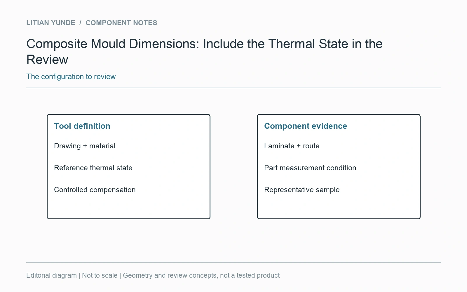
Identify which drawing defines the mould and which defines the delivered component. State the relevant inspection condition for each. A compensation built into a tool should be a controlled engineering decision, not an unexplained difference that another person later removes while updating the CAD model.
Use the proposed material and route
The review needs the actual tool construction, laminate definition and processing route where these affect dimensional behaviour. General material labels do not establish a universal compensation factor. Keep assumptions and the responsible review with the tool definition rather than transferring a correction from an unrelated mould.
Close the loop with representative evidence
A sample can help assess the proposed relationship when its material and process are identified. Record the actual part measurements and the conditions represented. If tooling or processing changes, check which conclusions still apply. This article supplies no numerical expansion coefficient, shrinkage allowance or processing schedule for an unspecified composite component.
Further reading: Hexcel: tooling material guide and test context.