
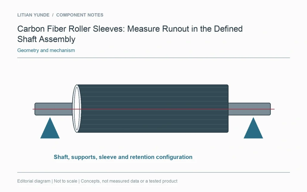
A roller sleeve’s installed runout depends on the defined shaft assembly and measurement reference. A loose sleeve dimension is useful, but it does not describe the complete rotating surface. Keep the shaft, end supports and sleeve attachment condition with the result.
Identify what rotates during the check
Show the shaft and the features that establish its rotational reference. Identify the sleeve position and how it is retained. If end fittings or another layer form part of the delivered roller, include them in the represented configuration rather than measuring an earlier loose component.
Locate the readings
Record where along the rotating surface readings are taken and which condition the measurement represents. The responsible review should establish the method and limits for the actual roller. Avoid comparing a bore measurement or free sleeve roundness entry directly with a whole-assembly runout result.
Keep replacement scope clear
If a spare sleeve is supplied separately, identify the shaft interface it must match and which final checks remain with the assembler. A different shaft or retention condition can change the represented setup. Keep the component records and assembled result connected, so an accepted sleeve is not automatically treated as an accepted roller system. This article gives no universal speed rating, load rating or runout tolerance.
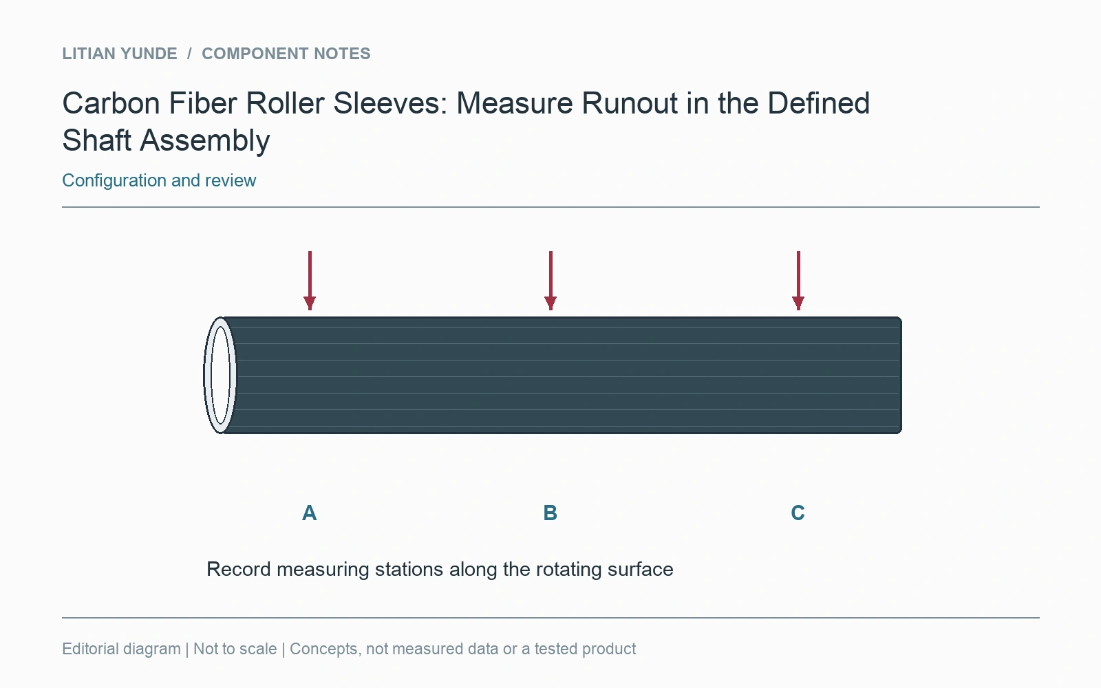
For the project review: shaft and rotational reference; sleeve position and retention; measuring stations and assembled condition; replacement interface and final-check responsibilities.