
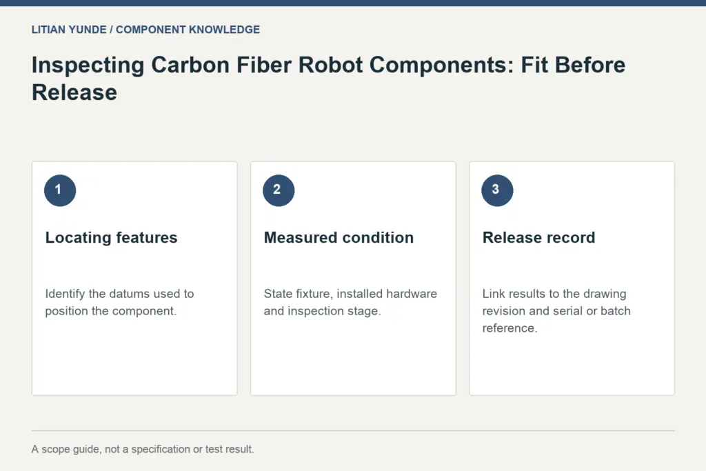
Editorial scope guide. The points are also available as readable text below.
For a robot component, an inspection report is most useful when it identifies the mounting features and clearances that affect the assembly. A photograph of an attractive surface cannot substitute for these checks.
Build the inspection plan from the mating parts
Mark the holes, locating faces and envelope that control the component’s position. Agree how the part will be supported during measurement and whether inserts or brackets are installed at that stage. Inspection in a different fixture can make two otherwise reasonable reports difficult to compare.
Separate acceptance from system performance
List dimensional checks, surface checks and any assembly trial as separate results. Robot repeatability, payload and cycle-time claims belong to the complete validated system. If a supplier changes the mounting arrangement, record that change for the integrator before treating the replacement as interchangeable.
Example scenario
A hole pattern measures correctly on a loose part but does not align after the specified bracket is fitted. Record the installed hardware and the agreed measurement condition so the drawing, fixture and inspection report refer to the same assembly.
Points to record
| Locating features | Identify the datums used to position the component. |
|---|---|
| Measured condition | State fixture, installed hardware and inspection stage. |
| Release record | Link results to the drawing revision and serial or batch reference. |
Related reading
- First-Article Inspection for Carbon Fiber Parts: Agree the Record Before Production
- A CNC Drawing Checklist for Custom Carbon Fiber Components
Background reference: Gurit — Composite Materials.
Discuss the component requirements
Send the part drawing and the requirements relevant to this guide for a scope review.
Contact Litian Yunde