Component overview
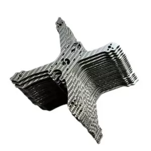
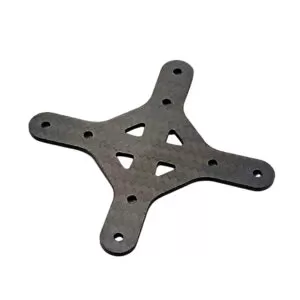
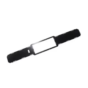
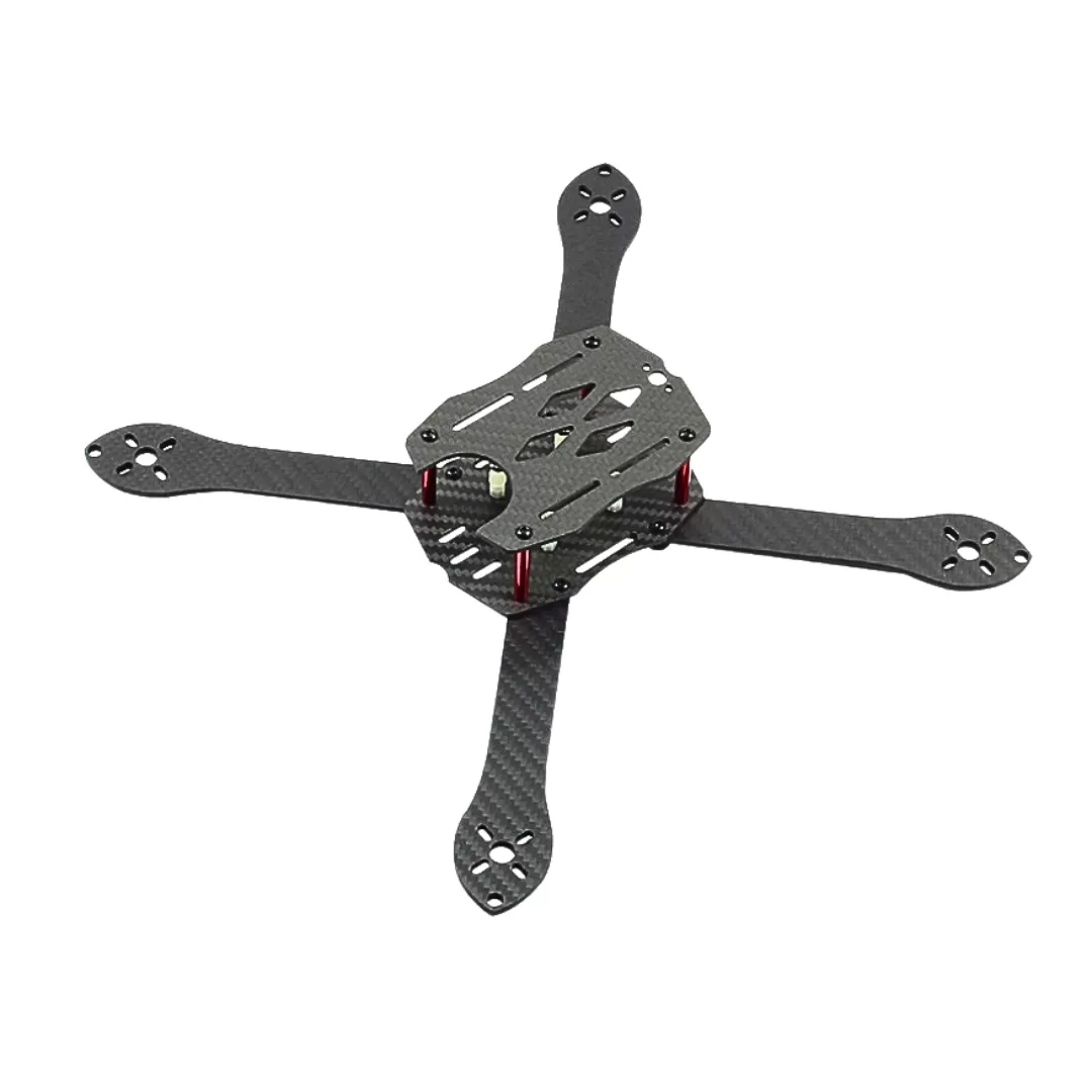
Frame-kit reference with arm and centre-plate geometry. Confirm the supplied component set and the system-specific design requirements before any operational use.
Define the installation, not only the outline
Show where the part sits in the assembly, the features that locate it and the clearances needed for wiring and service. Use common datums for mating holes and interfaces.
Details to include in your enquiry
| Feature | Information to provide |
|---|---|
| Component list | List plates, arms, spacers and hardware with separate part identifiers. |
| Motor and payload interfaces | Show motor, payload and equipment interfaces with required clearances. |
| Hardware scope | Clarify which screws, spacers and connectors are included in the requested kit. |
| System verification | Define fit checks and the complete-system verification plan separately from part inspection. |
Sample review and acceptance
Mark the critical dimensions and identify any separate insulation, inserts or hardware. Agree what is measured on the component and what is checked after assembly.
Separate sample and production quantities, identify the governing drawing revision, and list the inspection records you need. If a feature is not yet defined, mark it for discussion before quotation.
Questions about this component
Can the reference be adapted to my drawing?
Submit the drawing and highlight differences from the pictured reference. Geometry, material construction, finish and supplied hardware are reviewed together for the requested configuration.
What is included in the quotation?
Ask for the carbon fiber component, tooling where relevant, finishing, hardware, inspection and packing scope to be listed clearly. A reference image does not define every supplied item.
Product reference images. Dimensions, construction and supplied items are defined by the agreed drawing and quotation.
Prepare the next step
Read related technical and purchasing guidance · View the manufacturing workflow