
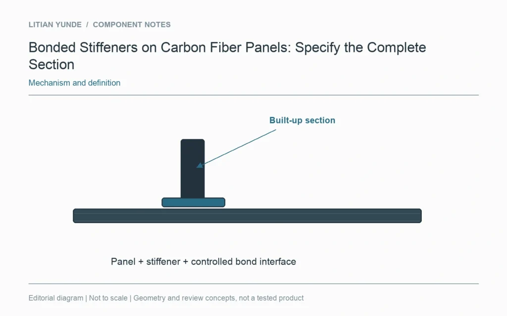
A bonded stiffener changes a flat panel into a built-up section. Its shape, position, bond interface and connection to the supports belong in the definition. Quoting only the plate thickness leaves most of that assembly unspecified.
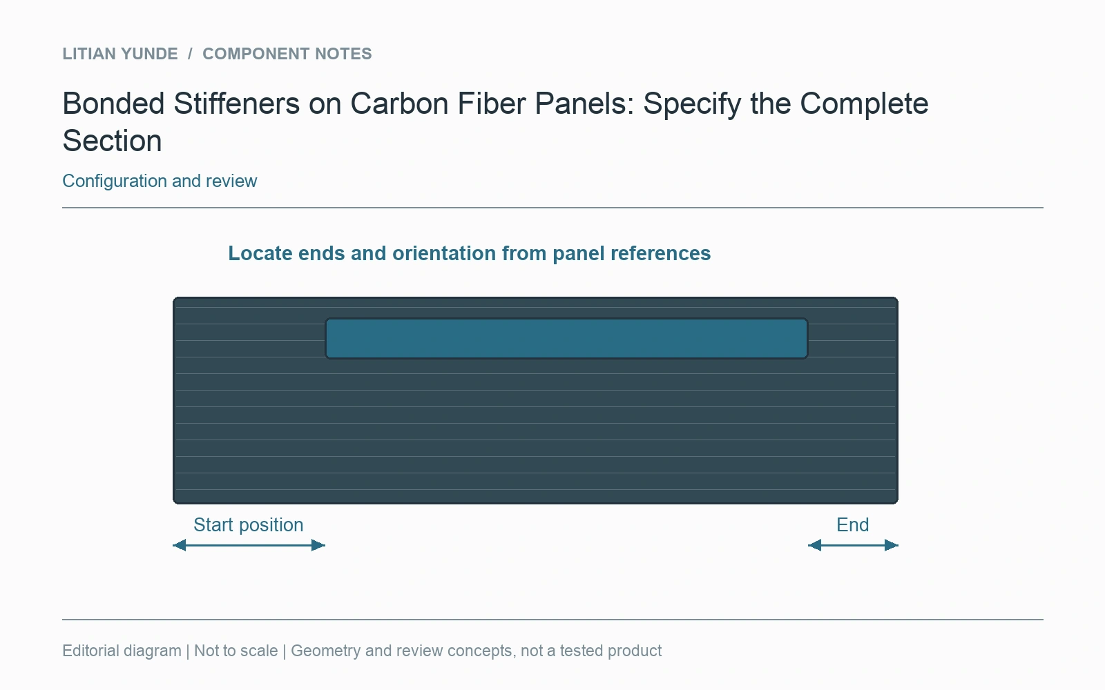
Show where the stiffener starts and ends
Locate the member relative to the panel datums and identify its orientation. End positions and clearances matter when the panel sits near fasteners, edges or removable covers. A simple section view can explain information that an overall plan view hides.
Define the supplied interface
The panel, stiffener and adhesive arrangement should be reviewed as one assembly. Keep the material and surface requirements with the agreed joining process. Do not treat a generic bead in a CAD picture as a controlled bond definition or assume a bare stiffener is included in a panel quotation.
Review the installed configuration
State how the assembly is supported and loaded, and which face is cosmetic or used for contact. Inspection may need to cover position, assembled shape and the agreed joint requirements. A result for an unstiffened plate is not automatically evidence for the completed built-up part. Keep samples and their construction records together when moving from prototype review to repeat production.
For the project review: stiffener section and orientation; located ends and clearances; bonded interface definition; installed supports and acceptance scope.