
A colour comparison between a scan and nominal CAD geometry needs an identified alignment and evaluation rule. The colours show a result within that setup; they are not self-explanatory acceptance labels. Keep the reference scheme and actual measured coverage with the report.
Distinguish alignment choices
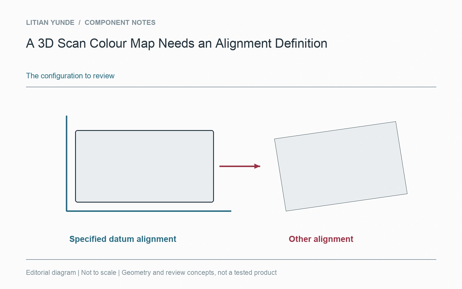
A comparison fitted broadly to a surface can answer a different question from one referenced to specified assembly datums. State which approach is required for the feature under review. Do not change alignment merely to obtain a more favourable-looking colour map, or infer assembly fit from a comparison that used another reference.
Show the evaluated surface
Retain the measured coverage, excluded regions and the part condition during scanning. The nominal model revision, units and display scale also belong with the result. Areas without usable measurement data should not be interpreted as passing regions simply because they are absent from the picture.
Make the conclusion readable
Identify which features were evaluated and the requirement supporting the disposition. A shape comparison is useful evidence, but it may not replace every required dimensional or functional check. NIST publishes work on performance testing of optical coordinate systems; that background reinforces the need to retain the method context rather than relying only on the density or visual detail of a point cloud.
Further reading: NIST: optical coordinate measurement system performance.