
Механическая обработка и сборка · Руководство по проверке компонентов · Litian Yunde
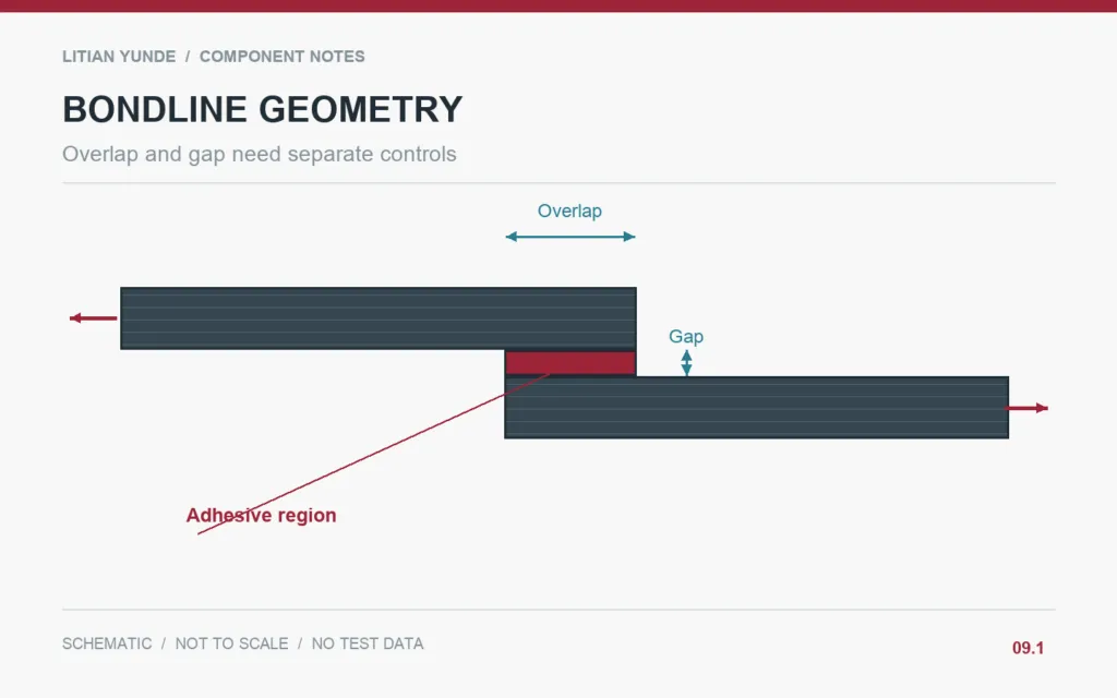
Overlap and gap need separate controls. Original explanatory schematic; not to scale and not a product test result.
A bonded carbon fiber joint should define both overlap and the adhesive gap. More overlap is not a complete joint specification, and a visually thin glue line is not automatically better. Use the adhesive supplier’s instructions and validate the actual joint configuration.
Draw the joint section
Show the adherends, bond area, gap control and any fillet or adhesive exclusion zone. Include the direction and type of loading for engineering review. A lap-joint sketch should distinguish the structural bond from cosmetic edge finishing. The design authority should establish dimensions and acceptance limits; a procurement article cannot supply universal overlap or bondline values.
Connect geometry with the bonding process
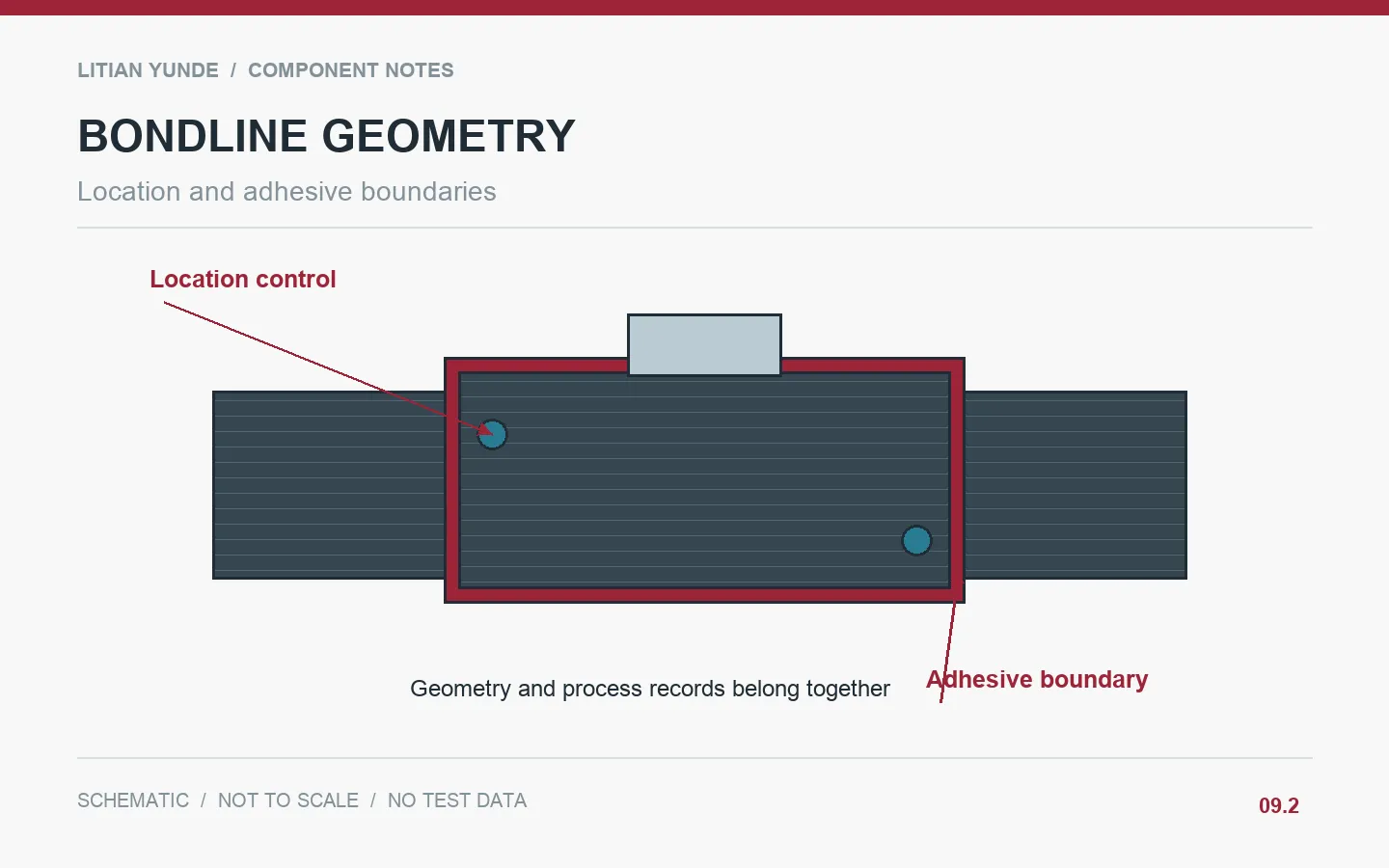
Clarify how parts are located without unintentionally squeezing the adhesive out of the intended region. Record surface preparation, adhesive identification and curing instructions in the approved process. WEST SYSTEM’s preparation guidance emphasises suitable clean, dry, prepared surfaces for its epoxy systems. Use the selected adhesive manufacturer’s requirements for the actual materials rather than transferring a generic sanding recipe.
Make evidence match the joint
Specify what can be checked directly and what needs process records or a representative test. External squeeze-out alone does not prove complete internal coverage. A test coupon can support a process review, but its geometry and preparation need to represent the relevant variables. Keep the sample report attached to the exact joint revision and adhesive configuration.
Example: a bonded mounting foot
A foot sits at the correct location but tilts as it is clamped during cure. The next fixture controls its position and the specified adhesive gap independently. The inspection package records fixture setup, adhesive batch and the agreed checks. The fix is a controlled assembly method, not an instruction to apply more adhesive by eye.
Это примерный сценарий, а не реальный случай из практики клиента или официально опубликованные производственные результаты.
Детали, которые необходимо согласовать перед оформлением заказа
| Обзор товара | Зафиксировать для согласования |
|---|---|
| Joint definition | Overlap, gap, load direction and adhesive boundaries. |
| Process record | Preparation, adhesive identity and cure conditions. |
| Location control | Fixture contacts and gap-control method. |
| Проверка | Inspection coverage and representative test requirements. |
Вопросы, которые задают покупатели
Does more adhesive always strengthen the joint?
No. Follow the qualified joint design and adhesive process.
Can squeeze-out be the only acceptance check?
It confirms adhesive is visible at an edge, not that the internal joint meets all requirements.
Техническая информация и рекомендуемая литература
Справочный материал: WEST SYSTEM: Подготовка поверхности. Приведенный выше контрольный список проекта и пример носят рекомендательный характер; данный документ не является сертификатом для компонента Litian Yunde.
- Bonding or Mechanical Fastening? Framing a Composite Assembly Review
- Резьбовые вставки из углеродного волокна: момент затяжки, выдерживаемое усилие вытягивания и количество рабочих циклов
- Ознакомьтесь с информационным центром по углеродному волокну
Обсудите свой компонент с Литянь Юнде
Сообщите нам о внесениях в чертеж, предполагаемом применении, а также о вопросах, касающихся интерфейса или приемки, которые необходимо решить. Приведенные требования к конструкции и приемке подтверждены для данного конкретного проекта.