
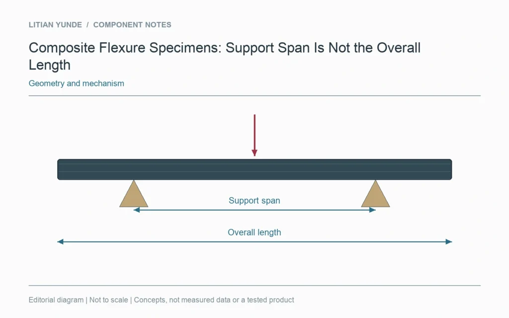
For a composite bending test, record the support span separately from the specimen’s overall length. The overhang beyond the supports does not belong in the support-span dimension. A specimen photograph needs labelled contact positions before it can communicate the test geometry.
Dimension the contacts
Show the distance between the defined support positions along with the specimen length, width and thickness. In a four-point arrangement, retain the loading geometry too. Do not infer a support location from the outer edge of a fixture housing.
Keep the test method attached
ASTM D7264 identifies span-to-thickness considerations within a specific composite flexure method. The applicable edition and procedure belong on the test record. This general guide does not replace that standard or prescribe a span for an unidentified specimen.
Compare like configurations
When two reports show different bending results, check their specimen and fixture geometry before treating the numbers as interchangeable. Cutting a longer coupon does not by itself define the distance between supports. If a setup was adjusted for a trial, retain the actual configuration and the reason for the change with the result. That makes the test interpretable without relying on a cropped image of the broken sample.
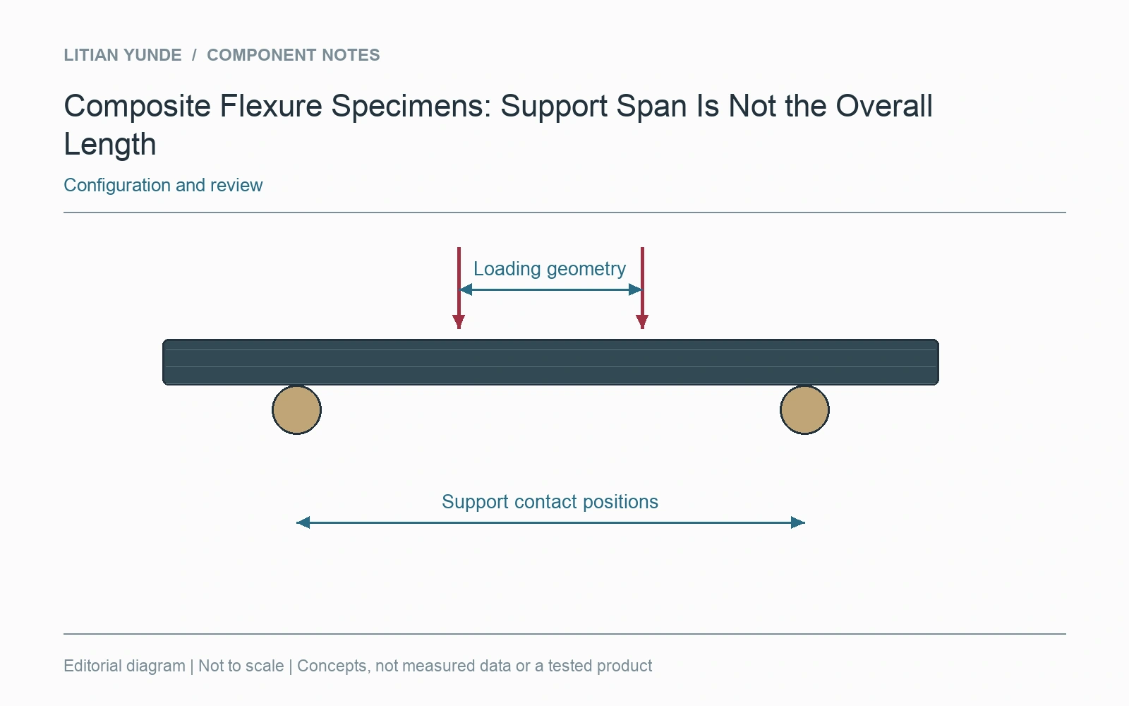
For the project review: support contact positions and span; overall specimen dimensions; loading arrangement and method edition; actual trial configuration.
Further reading: ASTM D7264: composite flexure method scope.