
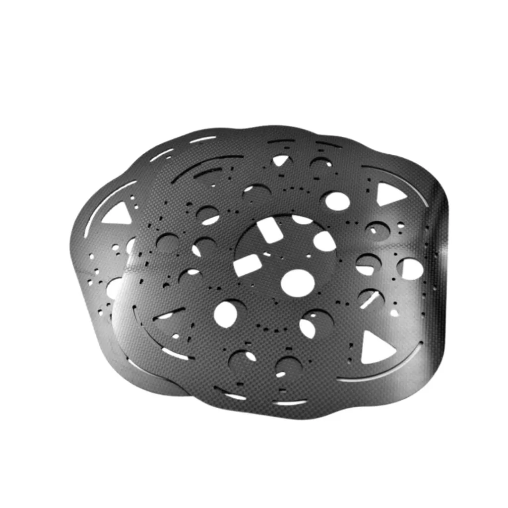
Curved perforated carbon fiber shell reference.
A robot cover needs more than a matching outer shape. Its openings, fixing points and removal path should allow the equipment to be assembled and serviced without damaging cables or the cover.
Map access in the assembled position
Mark the connectors, cable exits and service points behind the cover. Include the space needed for tools and hands, not just the nominal opening. For a split cover, identify the parting line and the order in which the sections are fitted.
Use the sample to test the service sequence
Review the cover with the intended fasteners and surrounding hardware in place. Record whether the cover can be removed without disconnecting unrelated parts. A shaped carbon fiber shell shown in a catalogue is a geometry reference; it does not demonstrate guarding, electrical or machine-safety compliance.
Example scenario
A connector fits through an opening, but its locking tab cannot be reached once the cover is installed. Review the connector’s operating space and the cover-removal sequence, not only the opening dimensions. Record the access check on the sample report.
Points to record
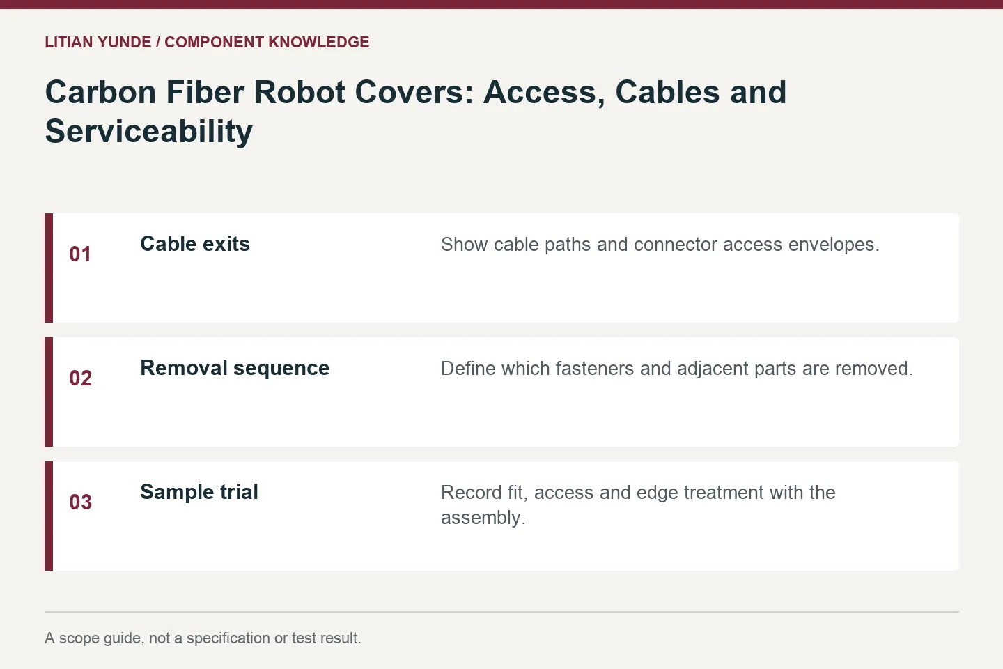
| Cable exits | Show cable paths and connector access envelopes. |
|---|---|
| Removal sequence | Define which fasteners and adjacent parts are removed. |
| Sample trial | Record fit, access and edge treatment with the assembly. |
Related reading
- Líneas de separación y bordes moldeados: análisis de una carcasa de fibra de carbono a medida
- Insertos en piezas de fibra de carbono: definir el inserto y su posición
Background reference: Gurit — Composite Materials.
Discuss the component requirements
Send the part drawing and the requirements relevant to this guide for a scope review.
Ponte en contacto con Litian Yunde