
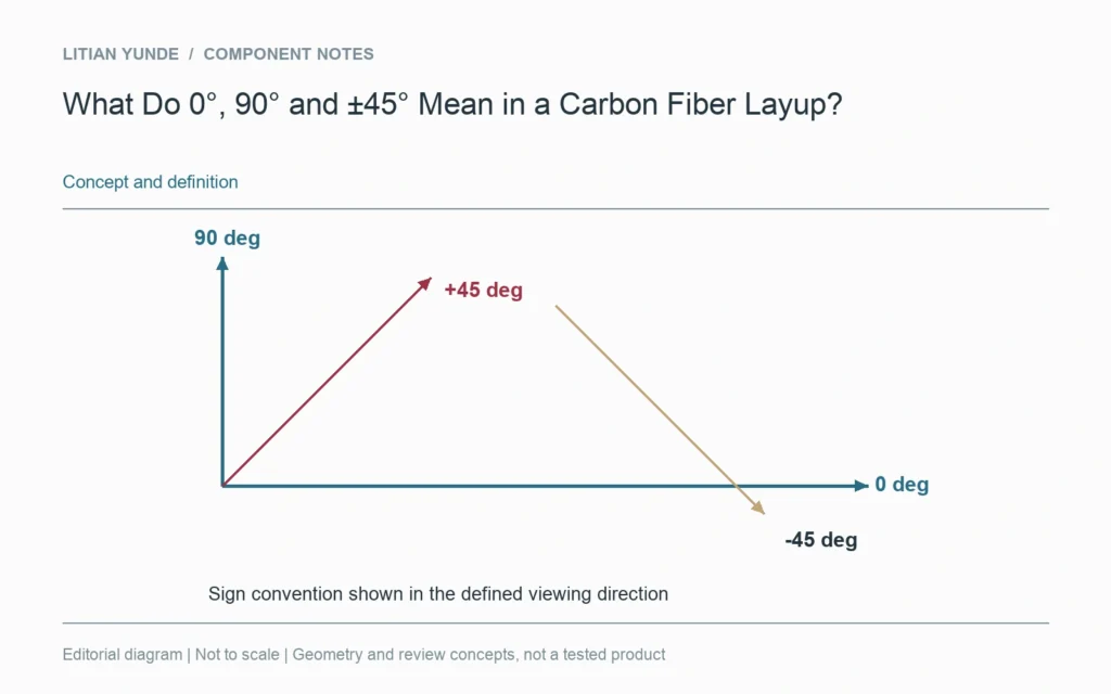
A ply angle only makes sense relative to an identified direction. In a laminate definition, 0°, 90° and ±45° describe orientations measured from that reference. They are not universal directions built into a finished component or a photograph of its weave.
Put the reference on the part definition
Choose a drawing axis, edge or other controlled reference and show the viewing direction. A ply-book reference and a CAD coordinate axis can otherwise be interpreted differently. When a plate is nested or a tube feature is clocked, carry the orientation information through the relevant manufacturing and assembly records.
Describe the reinforcement as well as the angle
A unidirectional ply has a principal reinforcement direction. A woven reinforcement includes yarns in more than one direction, so its orientation needs an appropriate fabric convention. The visible weave of an outer layer does not reveal the angles or materials in the rest of the stack. Keep the engineering definition separate from the cosmetic image.
There is no general-purpose best angle
Changing ply orientation changes laminate behaviour. The useful choice depends on loads, constraints, construction and the requirements being evaluated. Do not replace that review with a blanket instruction to add more 45-degree plies. For supplier discussions, show the reference system and state whether the layup is a controlled requirement or a proposal awaiting engineering review.
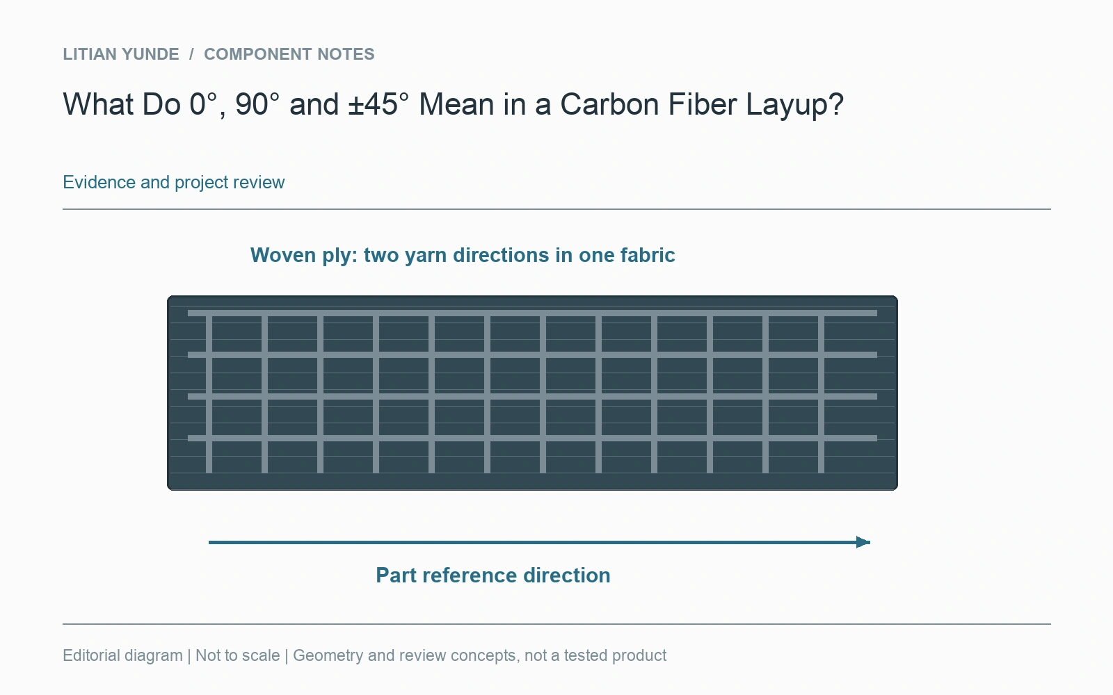
For the project review: angle reference and viewing direction; uD or woven reinforcement convention; controlled stack or proposed construction; loads and component requirements.
Further reading: NASA: composite laminate design guidance.