
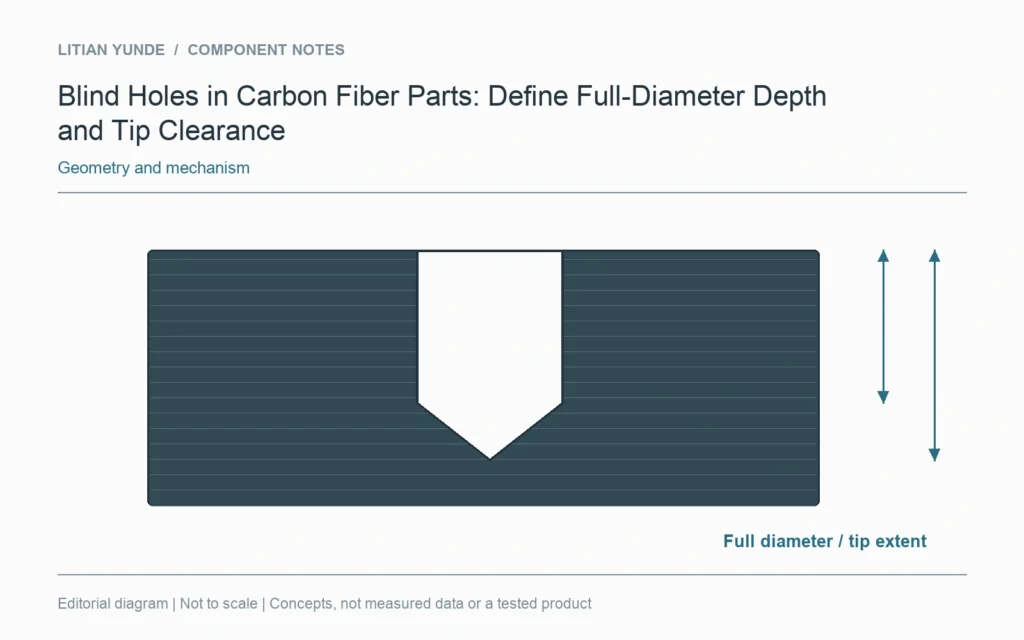
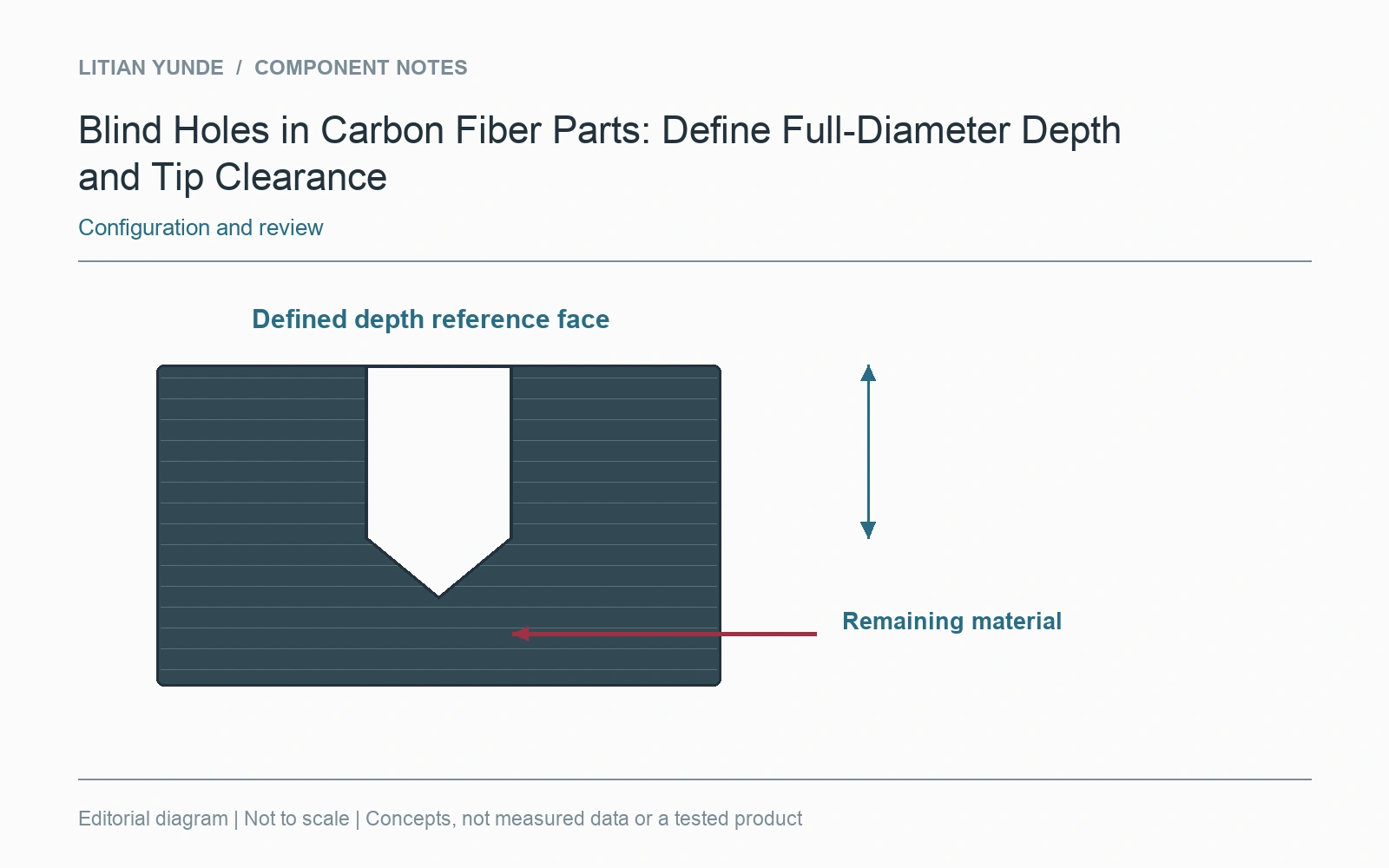
A drilled blind hole can have a full-diameter depth and a deeper drill-point extent. Show which dimension the part needs and how much material remains beneath the deepest feature. A simple depth number can leave those two boundaries confused.
Put the bottom geometry in section
Draw the cylindrical region and the intended bottom form. If the design needs a flat bottom, say so rather than leaving it implied by a depth label. Include the local finished section around the hole, especially near the opposite face or another cavity.
Check the manufacturing interpretation
Autodesk’s drilling documentation distinguishes depth to the tip from depth to the full-diameter portion. That software convention illustrates a question to settle with the supplier; it does not prescribe a drill geometry or process for every laminate.
Agree what can be inspected
Identify the surface from which depth is measured and the method used to check the relevant region. Keep the required functional engagement separate from the deepest material removal. A fitting that enters far enough does not establish the remaining wall beneath the drill point. Resolve any conflict between the requested depth, construction and measuring access before approving the manufacturing proposal.
Further reading: Autodesk: drilling depth to tip and full diameter.