
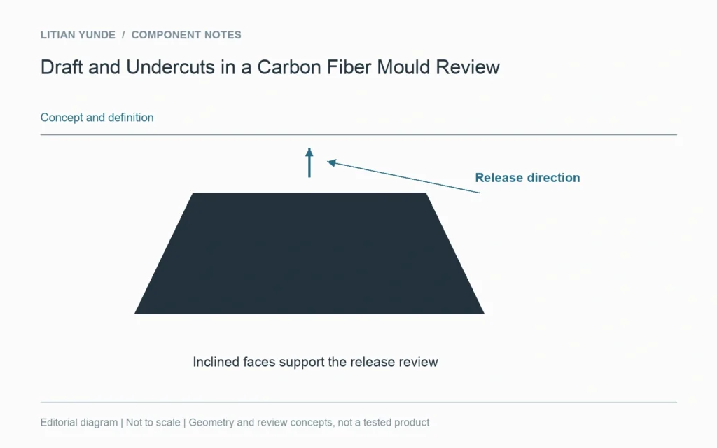
A finished shape has to leave its manufacturing tool. Draft is a geometric feature related to that release direction; an undercut can obstruct the path. Review the proposed tool and release movement together before assuming a smooth CAD shape is straightforward to mould.
Identify how each tool element and the part are intended to move during release. The same surface can be clear in one direction and trapped in another. A recommended draft from a particular tooling tutorial is not a universal value for every laminate, finish or moulding route.
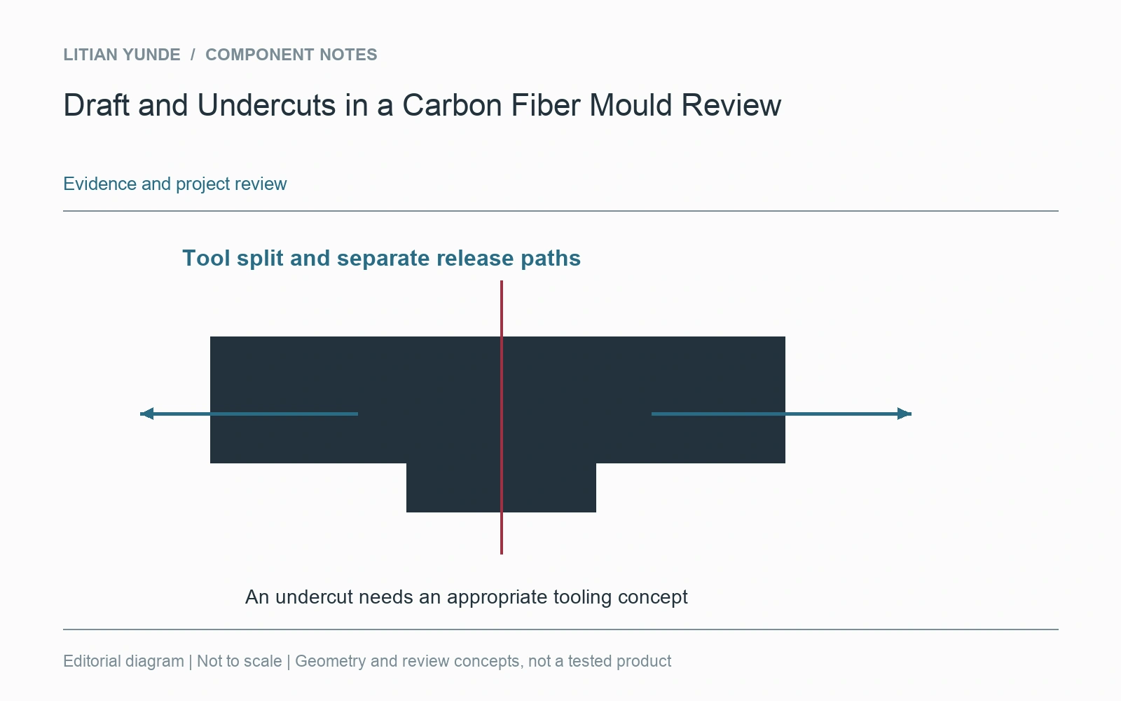
A split tool changes the geometry discussion
An additional tool split, removable element or different part arrangement may address an obstructed release path. Those choices affect alignment, surface witness lines and manufacturing work. They should be compared with the intended appearance and assembly interfaces, rather than treated as invisible details outside the component design.
Keep the supplied shape distinct from tool allowances
Trim allowance and temporary manufacturing features may exist outside the finished outline. Show which surfaces and edges control the delivered component. If geometry changes are proposed to improve release, record whether they affect the finished product or only the tool. This prevents a tooling discussion from quietly changing a mating face, visible edge or required clearance.
Further reading: Easy Composites: CAD techniques for composite mould design.